12
Mar
Mar
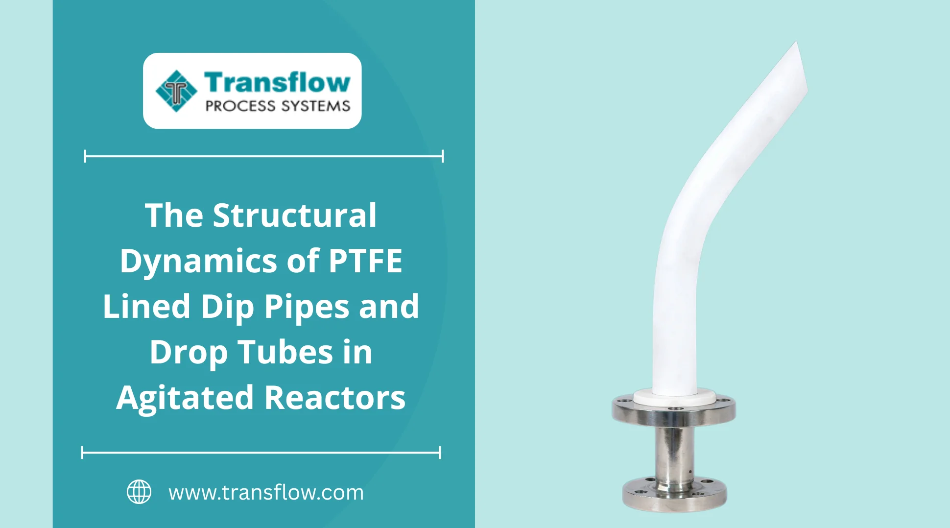
The Structural Dynamics of PTFE Lined Dip Pipes and Drop Tubes in Agitated Reactors
Standard corrosive service piping outside a vessel is predictable. You map the pressure, account for thermal expansion, and add your pipe supports.
Inside the reactor? Entirely different physics.
When you feed aggressive media into a highly agitated vessel, chemical compatibility charts give engineers a false sense of security. Just because a fluoropolymer resists hot acid doesn't mean the physical structure will survive continuous mechanical shear and fluid drag. This is why specialized engineering from Transflow Process Systems focuses on the mechanical integrity of the entire system, not just the material grade.
Here is why standard approaches to reactor feeding fail, and how process engineers mitigate these hidden structural stresses.
The Cantilever Problem: Bending Moments in the Vessel
A PTFE lined dip pipe typically fails in agitated service when the internal steel core flexes under fluid drag, causing the fluoropolymer liner to crease and eventually crack at the mounting flange.
Inside a mixing vessel, the feeding pipe acts as a cantilever beam. Heavy fluids rotating at high speeds create brutal lateral forces against the submerged lower half. Often, engineers specify a thin steel core to maximize the internal flow diameter, which proves catastrophic in agitated service. When fluid drag acts on the tube, the entire under-specified assembly flexes.
This continuous bending stresses the liner at the top nozzle. Over time, the plastic yields. It creases and thins out. This micro-creasing often takes months to expose the steel core.
A thicker liner doesn't always solve the problem. A stiffer steel core does. Preventing this requires specifying the exact structural schedule of the steel based on continuous bending forces, not just the baseline pressure rating of your broader lined pipe fittings.
Thermal Shock and Liner Separation
Lined drop tubes fail during thermal upset conditions because rapid temperature shifts create a localized vacuum, pulling the unreinforced plastic liner away from its steel housing.
Feeding cold reactant into a hot vessel creates immediate, localized stress. With standard exterior runs, temperature shifts are gradual. Inside the vessel, a lined drop tube or Dip Tube experiences instant thermal gradients. The exterior sits in boiling media while the interior is suddenly flushed with chilled fluid.
Plastic expands at a vastly different rate than steel. If the liner isn't heavily locked to the inner core, this rapid cycling causes it to pull away. Once separated, vacuum forces collapse the liner entirely.
That sounds obvious until it isn’t. Many standard specs completely miss the vacuum created during upset conditions. This is exactly why solid plastic piping simply snaps under the load. Surviving this requires a highly controlled unique lining process that ensures the paste-extruded PTFE maintains maximum crystallinity, preventing it from cold-flowing under shock.
The Upstream Interface Vulnerability
Even an over-engineered dip pipe is only as strong as its weakest connection. The kinetic forces captured by the dip pipe transfer directly upward into your piping infrastructure.
Engineers often upgrade the reactor feed but bolt it to an off-the-shelf nozzle. This approach breaks down when lining quality controls are inconsistent across spools and fittings. Treating the vessel feed as isolated from the upstream valving is a massive operational risk.
Back-pressure from a reactor feed is rarely smooth. Industry reliability studies on dynamic valves demonstrate that hinge wear accelerates up to 3x in the erratic flow conditions found directly above an agitated vessel. A standard lined swing check valve relying merely on a thin liner to protect its moving disc will chatter violently and fail prematurely under this stress.
The geometry of the upstream lined valves whether specifying a heavy-duty ball valve or a lined butterfly valve must match the robust integrity of the dip pipe below it. The reactor feed demands heavy-duty mechanical reinforcement from the nozzle up.
Decision Logic: Engineering the Upgrade
When an internal feeding component fails, replacing it with an identical specification is an operational risk. If you see liner creasing at the mounting flange, or vacuum collapse after thermal cycling, the component is mechanically under-designed for your vessel.
Replacing the spool with the exact same spec will only reset the clock on the next failure. More effort doesn't always fix this. Better engineering does.
Diagnosing the root cause requires a systematic look at the entire assembly. First, evaluate the agitation speed and fluid viscosity against the structural schedule of the steel core to prevent cantilever bending. Next, review the thermal delta between the incoming feed and the ambient vessel temperature to gauge the risk of vacuum collapse. High-stress reactor accessories demand intensive quality testing, including repeated electrostatic spark testing and structural verification, before they are ever installed.
Request a Structural Review
Do not wait for the steel core to breach. If you are experiencing liner creasing, vacuum collapse, or accelerated valve wear, contact our application team at Transflow Process Systems to calculate the required steel core schedule and lining architecture for your specific vessel geometry.