21
Mar
Mar
Eliminating Dead Legs in Reactor Drainage: A Guide to PFA and PVDF Lined Flush Bottom Valves
In fine chemical manufacturing, a dead leg is not just an inconvenience. It is a
contamination trap. If a valve at the bottom of a reactor fails to drain 100% of
the media, the residual fluid ruins the subsequent batch. Millions of dollars
are lost not because the chemistry failed, but because the mechanical drainage
system left a pocket of aggressive fluid behind.
Recently, we discussed the structural dynamics of PTFE
lined dip pipes and drop tubes and how to safely feed aggressive media
into an agitated vessel. But feeding the reactor is only half the battle.
Discharging that boiling, corrosive slurry requires a completely different
engineering approach.
Standard metal valves or generic lined plug valves often fall short in these
applications. Here is the engineering logic behind specifying lined flush bottom
valves, and why structural precision is the only way to ensure complete,
contamination-free discharge.
The Structural Problem: Cross-Contamination and Torque
A standard ball or plug valve bolted to the bottom of a tank naturally creates a
space between the reactor’s inner wall and the valve's sealing mechanism. Fluid
pools in this space. When handling sticky, high-viscosity, or highly corrosive
slurries, this dead space becomes impossible to flush out completely.
Furthermore, as these generic valves handle hot acids or abrasive slurries,
their operation stiffens. Operators are forced to apply massive torque to open
or close them, which stresses the valve stem and accelerates mechanical failure.
The Lined Flush Bottom Valve Solution
To eliminate the dead leg, the sealing mechanism must be positioned perfectly
flush with the inner bottom of the reactor. The fluid cannot be given any space
to pool.
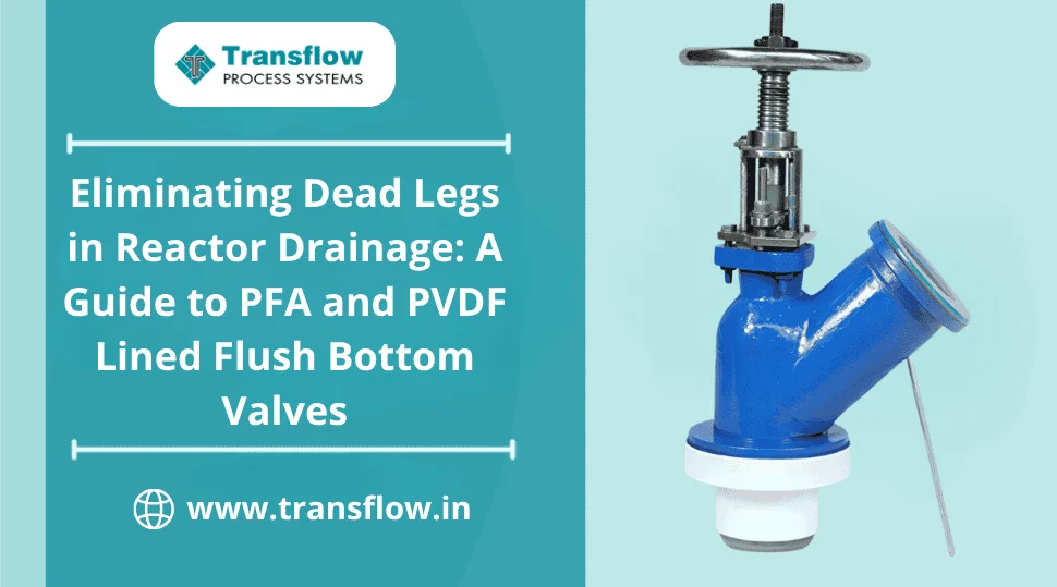
At Transflow, our Lined Flush Bottom
Valves are engineered specifically for complete discharge. The
interior valve bodies, as well as the stem and ball, are individually lined with
PFA or PVDF/FEP, creating a continuous, chemically inert
barrier between your aggressive process fluid and the metallic housing.
- The Housing: Available in heavy-duty Ductile Iron (ASTM A395) and Cast Carbon Steel (ASTM A216WCB).
- The Operational Advantage: Our design requires significantly lower torque for operation than equivalent plug valves, reducing operator fatigue and minimizing wear on automated actuators.
- Dimensional Compatibility: We engineered these with short pattern face-to-face dimensions following ANSI B16.10 and ANSI B16.5 (150 lbs). This means you can replace underperforming fully lined or sleeved plug valves without altering your existing PTFE lined pipe network.
High Vacuum Ratings: The Isothermal Injection Advantage
A flush bottom valve installed on a reactor will inevitably experience high
vacuum conditions, especially during thermal cycling. If the fluoropolymer liner
is loosely fitted or possesses residual stress, the vacuum forces will pull the
liner away from the cast housing, collapsing it instantly.
Transflow mitigates this failure mode through our unique lining process.
In our dedicated Vadodara facility, we utilize a semi-automatic, special-purpose
injection moulding machine equipped with a transfer system.
- Zero Residual Stress: The injection and transfer of plasticised material occur through a highly controlled isothermal process.
- Uniformity: Tooling assembly design guarantees that mandrels remain centrally located within the cast housing throughout the entire moulding stage. This results in uniform lining thickness across every valve body.
- Vacuum Integrity: Because of this injection technique, the PFA or PVDF liner fits intimately against the cast housing. This tight adherence is what gives the valve its high vacuum rating.
Validating the Engineering: Intensive Quality Testing
You cannot afford to guess if a valve will hold in corrosive service. It must be
proven before it leaves the facility. Our quality testing
protocol is designed to expose structural weaknesses before installation.
- Spark Testing: Prior to deployment, every single valve undergoes a rigorous electrostatic spark test at 15 KV DC (per ASTM F 1545-2003) to ensure there are zero pinholes in the liner.
- Hydro Testing: The structural integrity of the ductile iron or carbon steel housing is verified by subjecting the valve to 29 Kg/cm² of hydrostatic pressure for a duration of 3 minutes.
- Traceability: Every valve receives a hard punch encoding the year, month, and product serial number, accompanied by a Material Test Certificate (MTC) and Quality Control report.
Secure Your Reactor Discharge
Relying on off-the-shelf valves for reactor drainage is a deferred maintenance
problem waiting to happen. If you are struggling with dead legs, difficult
actuation, or liner collapse, it is time to upgrade the structural integrity of
your discharge system.
Contact Transflow Process
Systems to discuss the fluid dynamics of your agitated vessels and
specify a lined flush bottom valve built for complete, reliable discharge.